
ZigBee module introduction--TYZS3 Engineering version1. Product overviewThe TYZS3(Engineering version) is a low-power, embedded Zigbee module developed by Hangzhou Tuya Information Technology Co., Ltd. The module consists of a EFR32MG13P732 highly integrated wireless RF processor chip and a small number of peripheral devices. It has a built-in 802.15.4 PHY/MAC Zigbee network protocol and a large number of library functions. The TYZS3(Engineering version) embeds a low-power 32-bit ARM Cortex-M4 core, 512KByte Flash program memory, 64KB RAM data memory, and a wealth of peripheral resources.
The TYZS3(Engineering version) is a FreeRTOS platform that gathers all Zigbee MAC and TCP/IP libraries into one place. It enables users to build on the product and develop embedded Zigbee products that suit their individual needs.
The TYZS3 (Engineering Edition) supports the engineering version of the app configuration intelligent solution, batch-free network one-click configuration of equipment, scenarios, and apartment types; support engineering data management platform data visualization management, monitoring landing project progress, service stability.
The TYZS3 (Engineering version)schematic diagram as shown in Figure 1:
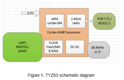
1.1 FeaturesA built-in low-power 32-bit ARM Cortex-M4 processor with a DSP instruction set and a floating point unit that doubles as an application processor
Supports a main frequency of 40MHzWide operating voltage: 1.8V-3.8V
Peripherals: 9×GPIOs, 1×UART, 1×ADC
Zigbee operating characteristics
Supports 802.15.4 MAC/PHYOperating channels 11 to 26 @2.400-2.483GHz, air-interface rate 250KbpsBuilt-in DC-DC circuit for maximum power efficiency+19dBm maximum output, dynamic power output > 35dB63uA/MHz operating power consumption; 1.4 uA sleep currentActive net pairing with terminal devicesBuilt-in onboard PCB antenna/reserved Ipex connector for high gain external antennaOperating temperature: -40℃ to 85℃Supports hardware encryption and supports AES 128/256
1.2 Primary application fieldsSmart buildings
Smart homes/appliancesSmart plugs, smart lightingIndustrial wireless controlHealth and measurementsAsset tracking2. Module interfaces2.1 Package dimensionsThe TYZS3(Engineering version) has 2 rows of pins with a 2mm gap.
TYZS3 (Engineering version)dimensions: 16mm (W) x 24mm (L) x 3.5mm (H). The TYZS3"s dimensions are shown in Figure 2:
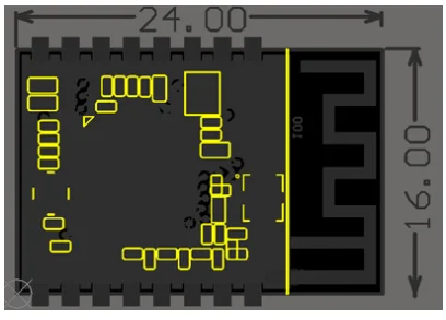
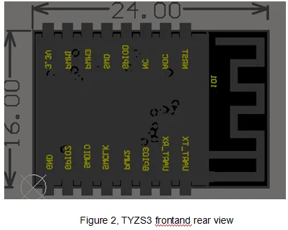
2.2. Pin definitionInterface pins are defined as shown in Table 1:
Table 1, TYZS3(Engineering version) interface pins description
Pin numberSymbolIO TypeFunction
1 nRST I Hardware reset pin, the chip is reset when the pin is LOW; Power-on reset of the module, the user can use this pin as needed
2 ADC AI ADC, 12-bit precision SAR analog to digital converter
3 NC - NC pin, external handling is not required
4 GPIO0 I/O GPIO pin usage.
5 SWO I/O GPIO pin usage/can be used as an output pin under JLINK communication.
6 PWM3 I/O GPIO pin usage.
7 PWM1 I/O GPIO pin usage.
8 VCC P Module power supply pin (common supply voltage: 3.3V)
9 GND P The reference ground of the module.
10 GPIO2 I/O GPIO pin usage.
11 SWDIO I/O JLINK SWDIO programming pin. Can be used as a GPIO pin in normal applications.
12 SWCLK I/O JLINK SWCLK programming pin. Can be used as a GPIO pin in normal applications.
13 PWM2 I/O GPIO pin usage.
14 GPIO3 I/O GPIO pin usage.
15 RXD I/O UART0_RXD
16 TXD O UART0_TXD
Description: P indicates the power pin; I/O indicates the input/output pin; AI indicates analog input pin.
nRST is only the module hardware reset pin; it cannot clear Zigbee net-pairing information.
(1): This pin can only be used as an ADC port. It cannot be used as a normal IO port. If it is not used, it needs to be left floating.
As an ADC input, the input voltage range is limited to 0-AVDD and can be configured by software.
2.3 Test point definitionTest pins are defined in Table 2:
Table 2, TYZS3(Engineering version) test pins description
Pin numberSymbolIO TypeFunction
- - I For module production testing
Description: This test pin is not recommended for use.
3. Electrical parameters3.1 Absolute electrical parametersTable 3, Absolute parameters
ParametersDescriptionMinimum valueMaximum valueUnit
Ts Storage temperature -50 150 ℃
VCC Input voltage -0.3 3.8 V
Electrostatic discharge voltage (human-body model) TAMB-25℃ - 2.5 KV
Electrostatic discharge voltage (machine model) TAMB-25℃ - 0.5 KV
3.2. Operating conditionsTable 4, Normal operating conditions
ParametersDescriptionMinimum valueTypical valueMaximum valueUnit
Ta Operating temperature -40 - 85 ℃
VCC Operating voltage 1.8 3.3 3.8 V
VIL IO low input -0.3 - VCC*0.25 V
VIH IO high input VCC*0.75 - VCC V
VOL IO low output - - VCC*0.1 V
VOH IO high output VCC*0.8 - VCC V
Imax IO drive current - - 12 mA
3.3 Zigbee TX power consumptionTable 5, Power consumption during continuous TX
SymbolRateTransmission powerTypical valueUnit
IRF 250Kbps +19dBm 120 mA
IRF 250Kbps +13dBm 50 mA
IRF 250Kbps +10dBm 32 mA
IRF 250Kbps +4dBm 17 mA
IRF 250Kbps +1dBm 11.8 mA
Note: When testing the above data, the continuous transmission duty cycle=100%.
3.4 Zigbee RX power consumptionTable 6, Power consumption during continuous RX
SymbolRateTypical valueUnit
IRF 250Kbps 8 mA
Note: When UART is active, the RX current is 14mA.
3.5 Power consumption in operating modeTable 7, TYZS3(Engineering version) operating current
Operation modeOperating condition, Ta=25℃Average valueMaximum valueUnit
Quick configuration Module in quick configuration state 10 40 mA
Network connection state Connected to a network - - mA
Deep sleep mode Deep sleep mode and retains 64KB Flash 1.4 3 uA
